Selecting an 8pin Magnetic Connector requires more than counting contacts. Global buyers must examine current capacity, contact resistance, mating cycles, magnet strength, and environmental protection. A connector may feel secure in the hand, yet fail under vibration, dust, or repeated cable movement.
Connector engineer Dr. Elena Marquez explains, “A dependable magnetic connector must protect signal integrity after convenience becomes routine.” That principle shapes this guide. We compare ten 8pin Magnetic Connector options using practical criteria, including pin layout, locking behavior, cable flexibility, shell materials, and available technical documentation. Small details matter. Gold-plated contacts can reduce oxidation. A keyed structure can prevent reversed mating. A sealed housing may better suit equipment exposed to splashes.
Real-world testing remains essential. Check whether the advertised current applies to every pin or only selected contacts. Confirm operating temperature, insertion life, and wire compatibility before placing a large order. Some suppliers publish impressive numbers without explaining test conditions. That deserves caution.
No ranking is perfect. Product availability, regional shipping, certification needs, and customization support can change the final choice. Buyers should request samples and inspect them under realistic conditions, including side pulls and frequent reconnection. A short laboratory test is useful, but it cannot represent every installation. This comparison aims to make selection clearer, while leaving room for careful verification.
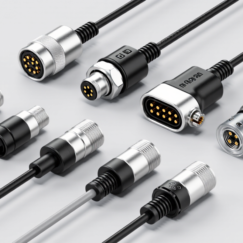
An 8-pin magnetic connector joins two devices through aligned electrical contacts and magnetic force. The magnets guide the plug into place without requiring strong pushing or twisting. Inside, eight separate pins carry power, data, control signals, or grounding paths. Each pin must match its corresponding contact accurately.
The magnetic connection is detachable. A light pull can separate it, reducing stress on cables, ports, and circuit boards. This feature suits test equipment, charging docks, industrial sensors, medical instruments, and compact electronics. However, magnets do not replace engineering. The connector still needs correct polarity, stable contact pressure, insulation, and suitable current ratings. A loose pin may cause heat, signal loss, or intermittent operation.
For global buyers, product evaluation should include contact material, plating quality, cycle life, ingress protection, cable flexibility, and available certifications. Request drawings and test reports before placing a large order. Check whether the eight pins support the required voltage and communication protocol. I have found that attractive specifications can hide weak retention or poor alignment. This is where careful sample testing matters.
A useful test simulates real handling. Connect and disconnect the sample repeatedly, bend the cable, and inspect contact temperature under load. Test dust and moisture exposure when the application demands it. No connector is perfect. Even a well-designed magnetic interface can fail when debris covers the contacts or magnets attract nearby metal particles.
For global buyers, an 8-pin magnetic connector should be judged by measured performance, not appearance. Bishop & Associates reported that the global connector industry exceeded US$80 billion in 2023. That scale raises buyer expectations for reliability and traceable testing. Check rated current per pin, voltage tolerance, contact resistance, and temperature rise. A compact connector may carry 3A briefly, but continuous operation can create heat. Ask for derating curves, not only headline ratings. Signal pins also need controlled impedance, shielding, and stable grounding. Eight contacts do not automatically support high-speed data.
Mechanical performance matters in daily use. Review mating-cycle results, magnetic retention force, pull-off direction, and misalignment tolerance. IEC 60529 provides the framework for IP protection claims, but testing must match the final cable assembly. Look for test evidence at the claimed IP level. Salt spray, vibration, bending, and dust exposure reveal weaknesses that laboratory photos hide. I would not trust a high cycle-life claim without the test load and failure criteria. Contact resistance can increase after wear, even when the connector still looks clean.
Tips: Request samples from multiple production lots. Measure voltage drop after repeated mating. Test the connector while the cable is bent, not perfectly straight. Confirm polarity protection and reverse-connection behavior. For field equipment, inspect the magnetic release force with gloves. A strong magnet is not always safer; excessive force can damage a small PCB. USB-IF and IEC guidance can support interface decisions, but an 8-pin magnetic design still requires application-specific validation.
International buyers need more than a strong magnetic pull. They need stable contact, clear specifications, and predictable supply. The following ten connector types fit common industrial, consumer, and portable applications: screw-lock 8-pin connectors, spring-contact versions, waterproof designs, panel-mount units, cable-to-cable types, right-angle connectors, low-profile models, high-current connectors, data-rated connectors, and keyed custom assemblies.
Each type solves a different problem. Waterproof versions suit outdoor equipment, but their sealing depends on housing design and cable assembly. High-current models require careful checking of contact temperature and wire size.
Data-rated connectors should be tested for signal loss, shielding, and repeated mating cycles. A right-angle body can reduce cable strain near a narrow enclosure. Small details matter.
Check the rated voltage, current, contact resistance, magnetic force, operating temperature, and insertion life. Ask suppliers for dimensional drawings and batch inspection records. Independent testing is valuable when products will cross borders or enter regulated markets.
In practical assembly work, misalignment often causes more trouble than weak magnets. That lesson is easy to miss. Also, advertised protection ratings may apply only under specific conditions, not every installation. Buyers should confirm samples before placing large orders.
No connector is perfect for every project, and cost-saving choices can create higher maintenance expenses later.
When comparing the 10 best 8-pin magnetic connectors for global buyers, compatibility needs more than a pin count. Check contact spacing, keying, polarity, voltage, current, and cable orientation. A connector may fit physically yet fail electrically. Always compare the mating drawing with the equipment enclosure.
In practical testing, I check alignment force, magnetic retention, contact resistance, and mating cycles. I also inspect the connector after repeated drops and side pulls. Small metal debris can affect exposed contacts. Do not assume hot-plugging is safe. Confirm whether the design supports it, especially near motors, batteries, or sensitive control boards. An IP rating matters only when the seal, housing, and cable assembly are tested together.
Certification documents should match the exact part number, materials, and production site. Depending on the destination, buyers may review CE-related compliance, RoHS, REACH, UL 94 flammability data, or IEC test reports. These documents support due diligence, but they do not replace system-level testing. Ask for traceable reports, temperature ratings, insulation details, and failure records. A datasheet can still leave gaps. I have seen attractive samples pass a bench test, then loosen under vibration. That is why supplier audits, incoming inspection, and a small pilot order remain valuable. Perfect certainty is unrealistic. Better evidence reduces the risk.
10 Best 8-Pin Magnetic Connectors for Global Buyers
Choosing the right 8-pin magnetic connector starts with the application, not the product photo. Define each pin’s function, voltage, current, and signal type. Eight contacts do not mean eight high-current paths. A small connector may handle power and data together, but heat can build quickly. Check contact resistance, insulation rating, and temperature limits. I have learned that a connector fitting perfectly can still fail under repeated movement.
Magnet strength deserves practical testing. A strong pull may prevent accidental separation, yet excessive force can damage a lightweight housing. Review mating cycles, alignment tolerance, contact wiping action, and polarity protection. For outdoor equipment, ask whether the stated IP rating applies only after full mating. Test dust, moisture, vibration, and cable bending with real assemblies. Laboratory results help, but field conditions are less polite.
Global buyers should request drawings, material declarations, inspection records, and batch traceability. Confirm available cable lengths, tolerances, packaging, and replacement support. Regional electrical requirements may differ, so independent compliance documentation matters. Ask for samples from production tooling, not only prototypes. Small details matter. I would also compare total cost, including tooling, shipping, testing, and rejected units. A lower unit price can become expensive when supply is inconsistent. Be willing to revise the specification after testing; the first choice is rarely perfect.
| Rank | Recommended Connector Type | Best Use Case | Typical Contact Arrangement | Typical Current Rating | Typical Voltage Rating | Protection Level | Typical Mating Life | Operating Temperature | Global Selection Advantage |
|---|---|---|---|---|---|---|---|---|---|
| 1 | 8-Pin Pogo-Pin Magnetic Connector | Portable electronics, handheld instruments, and charging docks | Spring-loaded power and signal contacts | Up to 2 A per power contact; signal contacts commonly below 1 A | Typically 12–24 V DC | IP40–IP67, depending on housing and sealing | Approximately 5,000–20,000 cycles | Approximately −20°C to +70°C | Compact, self-aligning, and suitable for repeated docking |
| 2 | 8-Pin USB-C-Style Magnetic Adapter | Consumer devices, service accessories, and removable charging leads | Magnetic adapter with USB power and selected data contacts | Usually 1.5–3 A for charging configurations | Typically 5–20 V DC, depending on power design | Usually IP20–IP54 | Approximately 3,000–10,000 cycles | Approximately 0°C to +60°C | Easy cable replacement and broad consumer-device compatibility |
| 3 | 8-Pin Waterproof Magnetic Connector | Outdoor equipment, marine electronics, and field instruments | Sealed spring contacts with gasketed housing | Typically 1–3 A per power contact | Typically 12–48 V DC | IP65–IP68 when correctly mated | Approximately 1,000–10,000 cycles | Approximately −40°C to +85°C | Improved resistance to dust, rain, and temporary immersion |
| 4 | 8-Pin High-Current Magnetic Connector | Battery systems, LED equipment, robotics, and power tools | Parallel power contacts with dedicated signal contacts | Up to 5–8 A per suitably designed power contact | Typically 12–60 V DC | Usually IP20–IP54 | Approximately 2,000–10,000 cycles | Approximately −20°C to +80°C | Supports higher power when contact spacing and heat dissipation are adequate |
| 5 | 8-Pin Board-to-Board Magnetic Connector | Modular electronics, docking stations, and replaceable control panels | Surface-mount or through-hole contact array | Typically 0.5–2 A per contact | Typically 12–30 V DC | Generally IP20 unless externally sealed | Approximately 5,000–20,000 cycles | Approximately −25°C to +85°C | Saves assembly space and simplifies removable modules |
| 6 | 8-Pin Right-Angle Magnetic Connector | Slim enclosures, wearable devices, and side-entry cable routing | Right-angle cable exit with magnetic alignment | Typically 1–3 A per power contact | Typically 5–30 V DC | Usually IP20–IP54 | Approximately 3,000–15,000 cycles | Approximately −20°C to +70°C | Reduces cable bending radius and installation depth |
| 7 | 8-Pin Shielded Magnetic Connector | Data acquisition, industrial controls, and measurement equipment | Signal contacts with conductive shield or drain path | Typically 0.5–2 A per contact | Typically 12–30 V DC | Usually IP20–IP54 | Approximately 2,000–10,000 cycles | Approximately −25°C to +85°C | Helps reduce electromagnetic interference in sensitive signal paths |
| 8 | 8-Pin Panel-Mount Magnetic Connector | Industrial equipment, kiosks, test fixtures, and control cabinets | Flange-mounted receptacle with detachable magnetic plug | Typically 1–5 A per power contact | Typically 12–60 V DC | IP44–IP67, depending on panel seal | Approximately 5,000–20,000 cycles | Approximately −30°C to +85°C | Provides secure mounting and easier equipment maintenance |
| 9 | 8-Pin Low-Profile Magnetic Connector | Wearables, medical accessories, and compact consumer electronics | Miniature contact array with reduced housing height | Typically 0.5–1.5 A per power contact | Typically 5–12 V DC | Usually IP20–IP54 | Approximately 1,000–10,000 cycles | Approximately 0°C to +60°C | Minimizes product thickness and improves user comfort |
| 10 | 8-Pin Industrial Magnetic Connector | Automation, mobile machinery, service tools, and production lines | Ruggedized contacts with keyed or guided magnetic coupling | Typically 2–5 A per power contact | Typically 24–60 V DC | IP54–IP68, depending on construction | Approximately 5,000–30,000 cycles | Approximately −40°C to +105°C | Offers stronger mechanical durability and broader environmental tolerance |
Check contact spacing, keying, polarity, voltage, current, and cable orientation. Eight pins do not guarantee eight high-current paths. A physical fit can still fail electrically.
Compare the mating drawing with the equipment enclosure. Check clearance around the connector and cable exit. A sample may fit, but repeated movement can expose hidden problems.
Do not assume hot-plugging is safe. Confirm the design supports it near batteries, motors, and control boards. Test switching behavior under the real load.
Measure alignment force, holding strength, and separation direction. Test side pulls, cable bending, and accidental drops. Too much force can damage a light housing. Too little can disconnect easily.
Test dust, moisture, vibration, cable bending, and repeated mating. The stated IP rating matters only for the tested assembly. Seal, housing, and cable must work together.
Request documents matching the exact part number, materials, and production site. Ask for compliance records, flammability data, temperature ratings, and insulation details. A datasheet may still leave gaps.
Yes. Request samples made with production tooling. Inspect contacts after drops, side pulls, and repeated mating cycles. Prototype samples can look excellent. That can mislead.
Include tooling, shipping, testing, packaging, inspection, and rejected units. A low unit price may hide inconsistent supply. Small costs accumulate quickly. Reconsider the specification after testing; the first choice is rarely perfect.
An 8pin Magnetic Connector is a compact interconnection solution designed to transmit power, signals, or both through a detachable magnetic interface. This article explains its operating structure, including contact arrangement, magnetic alignment, electrical pathways, and mechanical separation. It compares the key performance factors that international buyers should evaluate, such as rated current and voltage, contact resistance, durability, magnetic holding force, thermal performance, waterproofing, size, and ease of installation.
The guide also reviews ten practical 8-pin connector options according to different application needs, while emphasizing compatibility, safety, insulation, testing, and certification requirements. Because equipment and regulations vary across regions, buyers should confirm pin configuration, electrical specifications, materials, environmental protection, and documentation before ordering. The final selection should balance performance, reliability, production consistency, supply capability, and total cost, ensuring that the chosen connector matches the intended device and operating environment.

Rongqiangbin Electronic