Choosing the best 4 Pin Magnetic Connector begins with the real conditions around your device. A connector used on a medical monitor faces different demands from one fitted to a handheld sensor. Cable movement, contact frequency, cleaning routines, and available space all matter. Small details matter.
“Reliable connection starts with understanding the application, not selecting a connector by pin count alone,” says David Stone, a senior interconnect design engineer with more than two decades of product-development experience. His point is easy to overlook. A four-pin design may carry power, data, grounding, or mixed signals. The internal arrangement must match the circuit, not merely the product drawing.
Look closely at magnetic force, contact resistance, current rating, voltage rating, and mating alignment. A strong magnet is not automatically better. Excessive pull force can strain a thin enclosure or damage a small PCB. Check whether the pogo pins remain stable after repeated mating cycles. Inspect the housing, too. Rounded edges may guide the connector smoothly, while exposed contacts can collect dust or moisture.
A practical test includes real cables, angled pulls, vibration, and repeated attachment. Do not rely only on laboratory figures. Your first choice may still be wrong after testing. That is normal. The best 4 Pin Magnetic Connector balances electrical performance, mechanical durability, user safety, manufacturing cost, and future service needs. This guide explains how to compare those factors without confusing attractive specifications with dependable field performance.
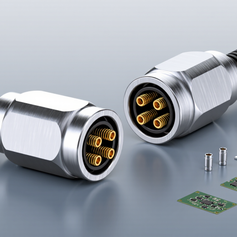
A 4 pin magnetic connector joins two devices through magnets and spring-loaded electrical contacts. The magnets guide alignment, while the pins transfer current or signals after contact. Four pins often support positive power, ground, and two communication lines. However, pin functions are not universal. Always verify the wiring diagram.
The connection feels simple. The engineering is not. Contact pressure, pin plating, magnetic strength, and cable movement affect reliability. A 2024 connector industry review by Bishop & Associates valued global connector sales at about 84 billion US dollars in 2023. This scale reflects growing demand for compact, detachable connections across electronics and equipment. Grand View Research also reports continued connector market growth through 2030, driven partly by miniaturized devices and faster data systems.
A practical inspection should check current rating, voltage rating, contact resistance, and mating-cycle performance. Magnetic alignment can reduce insertion errors, but it cannot replace correct polarity protection. Metal debris may collect around exposed contacts. That detail is easy to miss. Laboratory figures may also differ from real use, especially with vibration, moisture, or repeated side-loading. Choose a connector with a documented test method, not only an attractive specification sheet. A 4 pin design is suitable when power and data share limited space, yet it may fail when its thermal or mechanical limits are underestimated.
A four-pin magnetic connector should be judged by its working conditions, not its pin count. Start with voltage, continuous current, and peak current. Check the connector’s contact resistance under load. A small resistance can create heat inside a compact enclosure. Measure temperature rise after repeated connection cycles. Do not rely only on a catalog rating. Cable length and ventilation can change the result. Also confirm polarity, pin assignment, and protection against accidental reverse connection. A drawing may look clear, but assembly errors still happen.
Mechanical details often decide whether a connector survives daily use. Examine magnetic holding force, alignment tolerance, and separation direction. Strong magnets are not always better. Excessive force can stress a thin housing or pull a cable sideways. Look for a guided mating shape that centers the contacts before they touch. The connector should tolerate vibration without intermittent signals.
Test it while the cable bends near the joint. That is where failures commonly appear. Consider contact plating, spring travel, and rated mating cycles. These details affect long-term reliability more than appearance.
For wet or dusty equipment, verify the protection rating in the mated condition. Ask how the rating was tested. Was the cable moving? Was the connector repeatedly disconnected? Those questions matter. I would also inspect sample units, record contact resistance, and perform simple drop and flex tests. Results may expose weaknesses that specifications miss. Leave tolerance for manufacturing variation. A perfect prototype can become an unreliable production part. If the connector carries power and data, separate their pin paths when practical. Keep exposed metal away from likely touch points.
Choosing the best 4 pin magnetic connector starts with your device, not the connector itself. Identify the required voltage, current, signal type, and pin arrangement. A connector for charging may not suit data transfer. Check the device’s available space, too. A wide magnetic head can interfere with nearby buttons or protective covers.
Match the connector to the application environment. For wearable equipment, examine magnetic holding force, contact durability, cable flexibility, and resistance to dust or moisture. Industrial devices may need stronger alignment and a wider operating temperature range. Test the connector under real conditions, including repeated attachment, vibration, and accidental side pulls. Laboratory results help, but field use can reveal small problems.
Tips: Confirm polarity before assembly. Measure contact resistance. Leave room for cleaning. Test several samples, not just one. A connector can feel secure while still losing contact during movement. I once overlooked cable bending near the joint; the electrical design was correct, but the strain relief was too weak. That mistake showed why mechanical testing deserves equal attention. If the device requires stable data communication, monitor signal quality during connection and movement. A careful match improves safety, reliability, and user experience.
How to Match the Connector to Your Device and Application
| Application Type | Typical Electrical Requirement | Recommended Pin Allocation | Recommended Contact Rating | Ingress Protection | Retention and Alignment | Recommended Cable | Key Selection Advice |
|---|---|---|---|---|---|---|---|
| Wearable Electronics | 5 V DC; up to 1 A; low-speed charging or accessory power | 2 power pins, 2 low-speed signal or identification pins | At least 1.5 A per contact at the operating voltage | IP40 for dry indoor use; IP54 or higher for light outdoor exposure | Low-profile magnetic coupling with polarization to prevent reversed mating | Flexible 26–28 AWG cable, preferably with strain relief | Prioritize compact size, skin-contact safety, smooth surfaces, and controlled magnetic force. |
| Portable Consumer Device | 5–12 V DC; 1–2 A; charging and basic accessory communication | 2 power pins and 2 data or detection pins | 2–3 A per contact, with a suitable derating margin | IP54 for occasional splashes; IP65 when dust and water jets are expected | Polarized shell, keyed housing, and moderate pull-off force | 24–26 AWG stranded cable with reinforced jacket | Confirm the actual charging protocol; a four-pin connector does not automatically provide USB compatibility. |
| LED Lighting Module | 12–24 V DC; 2–5 A; power distribution or dimming control | 2 parallel power paths or 2 power pins plus 2 control pins | 5 A per contact, subject to temperature and cable-size limits | IP65 or IP67 for outdoor, industrial, or washdown locations | Strong magnetic alignment, mechanical keying, and anti-rotation features | 20–24 AWG cable, selected according to current, length, and voltage drop | Check heat rise carefully; contact rating, conductor size, and enclosure temperature must be evaluated together. |
| Small Sensor or IoT Device | 3.3–12 V DC; below 500 mA; low-level analog or digital signals | 2 power pins and 2 signal pins | At least 1 A per contact; verify signal-current and noise requirements | IP65 for dust and water exposure; IP67 for temporary immersion risk | Positive polarization with stable contact pressure and vibration resistance | 26–30 AWG shielded cable when low-noise or longer signal transmission is required | Evaluate contact resistance, shielding, grounding, and electromagnetic compatibility rather than current rating alone. |
| Robotics or Moving Equipment | 12–24 V DC; 1–3 A; repeated connection and vibration | 2 power pins and 2 control or feedback pins | 3 A per contact with a vibration-rated contact system | IP54 indoors; IP65 or IP67 for exposed machinery | Mechanical latch or secondary retention is preferred over magnetic force alone | High-flex 24–26 AWG cable with a flexible boot and controlled bend radius | Review mating-cycle life, cable flex life, vibration testing, and accidental-disconnection behavior. |
| Medical or Laboratory Equipment | 5–24 V DC; application-dependent current; reliable low-voltage power and signals | Power and signal allocation based on the approved electrical safety design | Use a rating with an appropriate safety margin and documented test results | IP54–IP67 depending on cleaning, fluid, and sterilization conditions | Controlled separation, clear polarization, and a predictable breakaway function | Cleanable, flexible cable with compatible jacket material and strain relief | Verify biocompatibility, cleaning-agent resistance, leakage current, isolation, and applicable regulations. |
| Industrial Control Panel | 24 V DC; up to 3 A; sensor, actuator, or auxiliary power connections | 2 power pins and 2 input, output, or diagnostic pins | 3–5 A per contact according to terminal temperature and duty cycle | IP65 or IP67 for dusty, wet, or washdown environments | Keyed housing, secure retention, and a clearly defined mating orientation | 22–26 AWG industrial cable with suitable insulation and shielding | Confirm creepage, clearance, dielectric withstand, flammability, and enclosure requirements before production. |
Choosing a 4 pin magnetic connector requires more than checking its appearance. Safety starts with controlled separation. A weak magnetic joint can detach during a sudden cable pull, preventing damage to the device. However, excessive magnetic force may stress a small socket or damage its housing. Test both conditions.
IEC 61984 provides safety requirements and test principles for connectors, while IEC 60529 defines protection levels against dust and water. Ask for verified test results, not vague claims. Measure contact resistance before and after repeated mating cycles. Inspect whether spring contacts remain aligned after twisting, vibration, and a one-meter drop. Small details matter. Gold-plated contacts can resist oxidation, but plating quality and thickness still require documentation. A connector may look premium and perform poorly.
Connection performance also depends on pin layout. Separate power and signal paths where possible, and check polarity protection before installation. The Global E-waste Monitor 2024 reported 62 million tonnes of electronic waste in 2022, with only 22.3% formally collected and recycled. Longer connector life can reduce replacement waste, although this benefit depends on the whole product design. My own selection process sometimes overvalues initial insertion feel. That is a mistake. Record contact resistance, retention force, temperature rise, and data stability under realistic loads. Repeat the test after contamination and cable bending. Real use is rarely clean.
Comparison of safety, durability, and connection performance using representative engineering reference values for common 4-pin magnetic connector designs.
Recessed-contact designs generally provide better protection against accidental short circuits and contamination. Higher mating-cycle ratings improve durability, while lower contact resistance and higher current capacity support more stable power and signal transmission. Always confirm the final choice with application-specific electrical, mechanical, and environmental testing.
Selecting a reliable 4 pin magnetic connector supplier requires more than comparing unit prices. Ask for complete datasheets, test records, and production traceability. A dependable supplier should state rated current, voltage, contact resistance, mating cycles, and magnetic holding force. Request samples from different production batches. One attractive sample proves very little.
MarketsandMarkets estimated the electronic connectors market at about USD 84.7 billion in 2024, with continued growth through 2029. Grand View Research also reports steady expansion, although its market estimates differ. That difference deserves attention. Industry figures depend on product definitions, regions, and research methods. Use reports as context, not as purchasing evidence.
Supplier audits should examine crimping equipment, incoming-material controls, and final inspection procedures. Ask whether testing follows relevant IEC 60512 methods for electrical and mechanical performance. Check insulation resistance, temperature rise, vibration results, and repeated mating performance. A supplier with ISO 9001 certification may offer stronger process control, but certification alone cannot guarantee connector reliability. During evaluation, test the connector under real cable bending and misalignment. A small contact failure can interrupt an entire device.
Choose suppliers that provide clear change-control notices, stable lead times, and responsive engineering support. They should explain current derating instead of quoting one impressive maximum value. Some suppliers avoid sharing failure data. That is a warning sign, though not absolute proof of poor quality. Reliable cooperation is visible in details: labeled samples, consistent dimensions, honest limitations, and traceable corrective actions.
Check working voltage, continuous current, and peak current. Measure contact resistance under the expected load. Small resistance can create heat inside a compact enclosure. Cable length and ventilation can change temperature results. Do not trust catalog ratings alone.
Higher resistance wastes energy and produces heat. This problem becomes serious in small, enclosed equipment. Measure resistance before and after repeated connection cycles. Record temperature rise during realistic operation. Tiny readings can still reveal future failures.
Test whether the connector separates during a sudden cable pull. A controlled release may protect the device and cable. Excessive force can damage a thin housing. It may also pull the cable sideways. Stronger is not always better.
Choose a guided mating shape that centers contacts before connection. Check alignment tolerance and separation direction. The connector should resist intermittent signals during vibration. Test it while bending the cable near the joint. That area often fails.
Inspect contact plating, spring travel, and rated mating cycles. Repeat connection tests under twisting and vibration. Add a one-meter drop test when appropriate. Check whether spring contacts remain aligned afterward. Prototypes can be misleading.
Confirm the protection rating in the mated condition. Ask how testing was performed. Was the cable moving? Were repeated disconnections included? Contamination and cable bending can expose weaknesses.
Separate power and signal paths when practical. Confirm polarity and pin assignments before assembly. Add protection against accidental reverse connection. Keep exposed metal away from likely touch points. Clear drawings still cannot prevent every assembly mistake.
Record contact resistance, retention force, temperature rise, and data stability. Test under realistic current, vibration, and cable movement. Repeat the measurements after contamination. Inspect sample units, not only documents. I sometimes overvalue initial insertion feel. That is a mistake.
Choosing the right 4 Pin Magnetic Connector requires more than checking its appearance or pin count. This type of connector uses magnetic force to guide and secure the connection while transferring power, signals, or both through four electrical contacts. Key considerations include rated voltage and current, contact resistance, data transmission capability, pin layout, magnetic force, alignment accuracy, dimensions, and cable flexibility. These specifications should match the device’s electrical requirements and the application’s space, operating environment, and connection frequency.
A reliable selection also depends on safety, durability, and consistent performance. Look for stable contact, protection against short circuits, resistance to vibration, corrosion, dust, and moisture when necessary, and a service life suitable for repeated use. When evaluating suppliers, review material quality, manufacturing consistency, testing procedures, customization support, documentation, and after-sales service. Comparing samples and verifying performance under real operating conditions can help ensure the connector delivers a secure, efficient, and long-lasting connection.

Rongqiangbin Electronic