How to Choose USB Pogo Pins for Global Sourcing in 2026? begins with a practical question: what must the connector survive every day? A Usb Pogo Pin may face repeated compression, dust, vibration, heat, and uneven alignment. Its tiny spring is not a minor detail. It controls contact stability, electrical resistance, and service life.
Dr. Elena Marquez, a connector design specialist, states, “A pogo pin is small, but its tolerance can decide the reliability of the entire USB connection.” This principle matters during global sourcing. Buyers should compare rated current, contact resistance, spring force, working stroke, plating thickness, and mating cycles. They should also confirm whether the design supports USB 2.0 or higher-speed signal requirements. Power contact performance alone is not enough.
Inspect the supplier’s drawings carefully. Look for shaft diameter, compressed height, tip geometry, and allowable tolerance. Ask for material certificates, plating details, inspection records, and test samples. A gold-plated contact may look dependable, yet poor spring consistency can still create intermittent charging. That assumption can fail.
Real testing exposes the gaps. Cycle sample parts inside the actual housing, not only on a laboratory fixture. Apply side loads and test after temperature changes. Measure voltage drop under realistic current. Global shipping adds another concern, including packaging damage and inconsistent batches. No spreadsheet replaces physical validation. Still, the spreadsheet helps reveal risks early. A reliable Usb Pogo Pin is chosen through evidence, not appearance or the lowest quoted price.
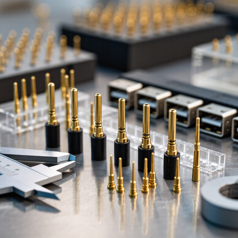
When choosing USB pogo pins for global sourcing in 2026, define the protocol before comparing suppliers. USB-C typically uses a 24-contact architecture, but the connector alone does not guarantee high-speed performance. A pin set for USB 2.0 needs to support 480 Mbps signaling, while USB4 designs may require transmission up to 80 Gbps. These are very different engineering problems.
For a 480 Mbps product, inspect contact resistance, spring force, plating thickness, and mechanical tolerance. Stable grounding matters, especially when the connector is repeatedly compressed. For USB4, ask for controlled impedance data, high-frequency test results, crosstalk measurements, and a complete mating-stack drawing. Tiny gaps can disturb signal quality. Request samples with the final housing, not loose pins only. That detail is often missed.
I have seen attractive samples fail after thermal cycling. The surface looked clean, but contact resistance increased after repeated compression. Do not trust a single insertion test. Require dimensional inspection, continuity checks, and protocol validation across temperature ranges. A supplier should provide traceable material records and consistent lot controls. For global sourcing, confirm packaging protection, inspection criteria, and replacement lead times in writing. Some specifications remain unclear until production begins. That is a sourcing weakness worth correcting early.
USB PD 3.1 can deliver up to 240 W at 48 V and 5 A. That 5 A is the key pogo-pin design target. Do not divide it blindly across contacts. A practical layout may use four pins for VBUS and four for return, placing about 1.25 A per pin under balanced conditions. Real assemblies need margin for uneven contact pressure, oxidation, and manufacturing variation. A 2 A-rated pin may not be suitable if its rating assumes short pulses or open-air cooling.
Thermal testing should be based on the complete mated interface, not a catalog number. Contact resistance matters greatly. At 5 A, 10 milliohms creates 0.25 W of heat in one current path. Keep the target temperature rise near 20–30°C where possible, then verify it after repeated mating cycles. Measure voltage drop at the pin interface with thermocouples attached nearby. I once treated parallel pins as perfectly equal. That assumption was too optimistic. Pin force, alignment, and housing stiffness can shift current between contacts. Request test data at the intended stroke, current, ambient temperature, and duty cycle. For global sourcing, compare these conditions directly, and require production samples before approving the design. Short tests can mislead. Real charging loads last longer.
For global USB pogo-pin sourcing in 2026, define geometry before requesting prices. Specify tip diameter, barrel diameter, overall height, working travel, and compressed height. A 1.5 mm tip may fit the pad, yet fail when housing tolerance shifts by 0.2 mm. Keep the pin aligned with the mating pad. Misalignment creates uneven wear and unstable contact resistance. Spring force must be measured at the actual working stroke, not at free height. Start with a force window, such as 60–100 gf, then validate electrical performance under vibration and compression. A larger force is not automatically better. It can deform thin circuit-board pads.
Plating requires equal precision. Specify a nickel underlayer, hard-gold thickness, contact-area coverage, and acceptable porosity. For repeated USB-style docking, 0.76 μm hard gold is a useful engineering reference, but the final value depends on current, humidity, debris, and cycle count. The USB-IF Type-C specification uses 10,000 mating cycles as a durability reference. IEC 60512 test methods can support contact-force and mechanical-cycle verification. Grand View Research’s 2024 connector-market report forecasts roughly 5.6% annual growth through 2030, increasing pressure for stable multi-region supply. Request lot-level force curves, plating certificates, dimensional inspection data, and samples from more than one production batch. A first sample can look excellent. That is not proof. I would also repeat testing after thermal aging, because this step is often underestimated.
Representative engineering targets for USB pogo-pin sourcing. Confirm the final geometry, force, plating system, signal integrity, and lifecycle requirements against the actual device design because these values are application targets rather than universal USB specifications.
Higher-speed USB applications generally require tighter geometric control, stable contact force, low-wear precious-metal plating, and more demanding mating-cycle validation. The values shown represent practical sourcing targets: contact-tip diameter in millimeters, working spring force in millinewtons, gold thickness in micrometers, and tested mating cycles.
When sourcing USB pogo pins in 2026, ask suppliers for test records tied to the actual contact design. IEC 60512 includes test methods for connectors, but the relevant methods depend on the product and its use. A generic pass certificate tells you little about your assembly. Request the test conditions, sample count, mating-cycle history, and stated acceptance limits.
Measure contact resistance with a four-wire method to reduce lead and fixture errors. Record readings before and after repeated mating, then compare results across samples. Keep the contact force, alignment, and measurement setup consistent. A pin that reads well on a clean bench may behave differently after wear or exposure to dust. Small details matter. Check plating condition and spring travel, too, since both can affect repeatability. Resistance alone does not prove reliable USB performance; verify current, temperature rise, and signal behavior at the assembly level where relevant. A single low reading is reassuring, not proof. I would also question unusually perfect supplier data if the procedure is unclear. Real tests are rarely that tidy. Tie each result to a drawing revision and a defined production lot, so sourcing changes do not quietly change the contact behavior.
| Sourcing Dimension | What to Specify or Measure | Example Screening Target or Reported Data | Validation Notes |
|---|---|---|---|
| USB application and signal map | USB generation, data rate, power role, pin assignment, grounding, and mating arrangement | Document each contact’s signal, maximum operating voltage, and expected current | Confirm the complete product’s USB interface and compliance requirements. A pogo-contact assembly is not automatically a compliant USB Type-C receptacle. |
| Initial contact resistance | Measure each contact using a four-wire (Kelvin) method at a defined current, force, and probe position | Example buyer-defined screen: ≤50 mΩ per contact; set the final limit from the circuit’s voltage-drop and power-loss budget | IEC 60512-2-1 describes a millivolt-level method for measuring contact resistance. Agree on the applicable procedure and limits with the supplier; the method itself does not set a universal pass limit. |
| Resistance after cycling | Measure resistance before and after the specified mating-cycle sequence | Example buyer-defined screen: ≤100 mΩ per contact after 10,000 cycles, if that cycle life matches the intended use | Treat cycle count and resistance limit as application requirements, not universal IEC acceptance criteria. Record sample count, stroke, speed, alignment, and test interruptions. |
| Contact continuity under movement | Monitor for intermittent opens while the mated assembly is exposed to the intended motion or vibration profile | Specify the maximum allowed interruption duration and the monitoring threshold in the test plan | Set the fixture, mounting, load, and monitoring bandwidth to represent the end product. Do not substitute a static resistance reading for a dynamic continuity check. |
| Rated current and temperature rise | Test the complete contact arrangement at the intended current, ambient temperature, and duty cycle | Record current per contact, temperature rise, stabilization time, and contact resistance before and after testing | There is no single current rating suitable for every pogo pin. Derating depends on contact geometry, pitch, neighboring loaded contacts, airflow, and the assembled design. |
| Insulation and dielectric performance | For isolated circuits, define insulation-resistance and dielectric-withstand tests for the assembled interface | Specify test voltage, duration, measurement points, and minimum insulation resistance based on circuit requirements | Select limits from the applicable product safety and circuit requirements; avoid applying an assumed generic value to every USB assembly. |
| Travel, force, and alignment | Specify working travel, available overtravel, spring force at working height, and allowable lateral misalignment | Request force-versus-travel data and confirm dimensions against the released mechanical drawing | Check that the tolerance stack-up maintains the required compression without bottoming out or losing contact. |
| Plating and wear | Identify contact and base materials, plating metals, minimum plating thickness, and any underplate | Require material declarations and plating-thickness test reports for production lots | Choose the finish for the mating material, environment, and cycle life. Verify wear and resistance after cycling rather than relying on a finish description alone. |
| Environmental robustness | Define applicable humidity, temperature cycling, contamination, and corrosion exposures | Record exposure conditions and compare continuity, contact resistance, and visible damage before and after exposure | Select severity and acceptance criteria from the intended operating environment and product qualification plan. |
| Global sourcing and lot control | Request a controlled drawing, revision history, material declarations, lot traceability, and a production inspection plan | Compare samples from at least three production lots when qualifying a new source, where schedule and risk justify it | Define change notification, approved test methods, sampling rules, packaging, and shipping conditions in the purchase specification. |
Note: Numerical screening targets shown above are examples for buyer-defined qualification plans, not universal IEC 60512 limits. Confirm the applicable edition, test method, fixture, and acceptance criteria for the specific assembly.
For USB pogo pins, qualify the supplier’s process, not just its catalogue rating. Ask for lot-level records linking spring alloy, contact plating, and assembly date. Request RoHS and REACH declarations for the exact pin configuration, including plating and solderable finishes. The European Commission’s RoHS rules restrict ten substances; ECHA’s Candidate List contained 247 entries in June 2025. REACH listing does not automatically mean a part is prohibited, so confirm substance-specific status and ask when declarations were last reviewed.
Traceability matters when contact resistance rises after repeated docking. Request plating-thickness results, material certificates, and inspection records tied to production lots. Then test samples at your actual current, temperature, and mating-cycle conditions. Paperwork can fail. A clean certificate cannot prove stable contact force across a full production run.
For 2026 capacity, request monthly output by line, current utilization, tooling status, and lead times for springs and plated contacts. Compare those figures with recent delivery records, not a sales forecast alone. Ask the supplier to run a pilot lot and report yield, dimensional variation, and electrical-test failures. IPC’s electronics manufacturing standards offer useful frameworks for process control, but your acceptance limits must match the device. Test the real stack. Even an experienced buyer may miss a weak link: capacity can look ample until one plating line becomes the bottleneck.
A 24-contact connector does not guarantee high-speed performance. USB 2.0 needs 480 Mbps support. USB4 designs may require up to 80 Gbps. These demands require different contact, impedance, and testing strategies.
Review contact resistance, spring force, plating thickness, and dimensional tolerance. Stable grounding matters during repeated compression. Inspect the complete connector assembly. Loose pins can hide housing-related problems.
Request controlled impedance information, high-frequency test results, and crosstalk measurements. Ask for a complete mating-stack drawing. Tiny gaps can disturb signal quality. Test final housings, not only loose contacts.
A 240-watt system can involve 48 volts and 5 amps. Treat 5 amps as a major design target. A balanced layout might use four power contacts and four return contacts. That equals about 1.25 amps per contact. Balance is not guaranteed.
Not automatically. The rating may assume short pulses or open-air cooling. Uneven pressure, oxidation, and manufacturing variation reduce practical margin. Evaluate the complete mated interface under the real duty cycle.
Measure voltage drop directly at the contact interface. Use nearby thermocouples during current testing. At 5 amps, 10 milliohms creates 0.25 watts of heat. A temperature rise near 20–30°C is a useful target. Still, verify the actual assembly.
Request tests matched to the actual contact design. Include mating-cycle history, sample quantity, test conditions, and acceptance limits. Measure resistance before and after repeated mating. Check spring travel, alignment, plating condition, current, and temperature rise. One low reading proves very little.
Attractive samples can fail after thermal cycling. Contact resistance may rise after repeated compression. Production samples reveal lot variation, housing stiffness, and alignment changes. Keep results tied to drawing revisions and material records. Perfect data deserves questions. Real testing is rarely so tidy.
Choosing the right Usb Pogo Pin for global sourcing in 2026 starts with clearly defining the required USB-C protocol. Determine whether the design needs a 24-pin interface, USB 2.0 performance up to 480 Mbps, or USB4 capability up to 80 Gbps. For USB Power Delivery 3.1 applications, translate the 240 W maximum into realistic current, voltage, temperature-rise, and derating targets so the contact system remains safe and stable under continuous load.
Next, specify the pin’s diameter, travel, spring force, plating, contact resistance, and expected mating cycles according to the mechanical environment. Reliability should be verified through IEC 60512 testing, repeated mating evaluations, vibration checks, and resistance measurements before and after environmental exposure. Finally, qualify suppliers by reviewing RoHS and REACH documentation, material traceability, process controls, quality records, and their ability to support required production volumes in 2026. A structured comparison of electrical, mechanical, compliance, and supply-chain capabilities will reduce sourcing risk and improve long-term product reliability.

Rongqiangbin Electronic